AutomataKit Stepper23 Circuit Design
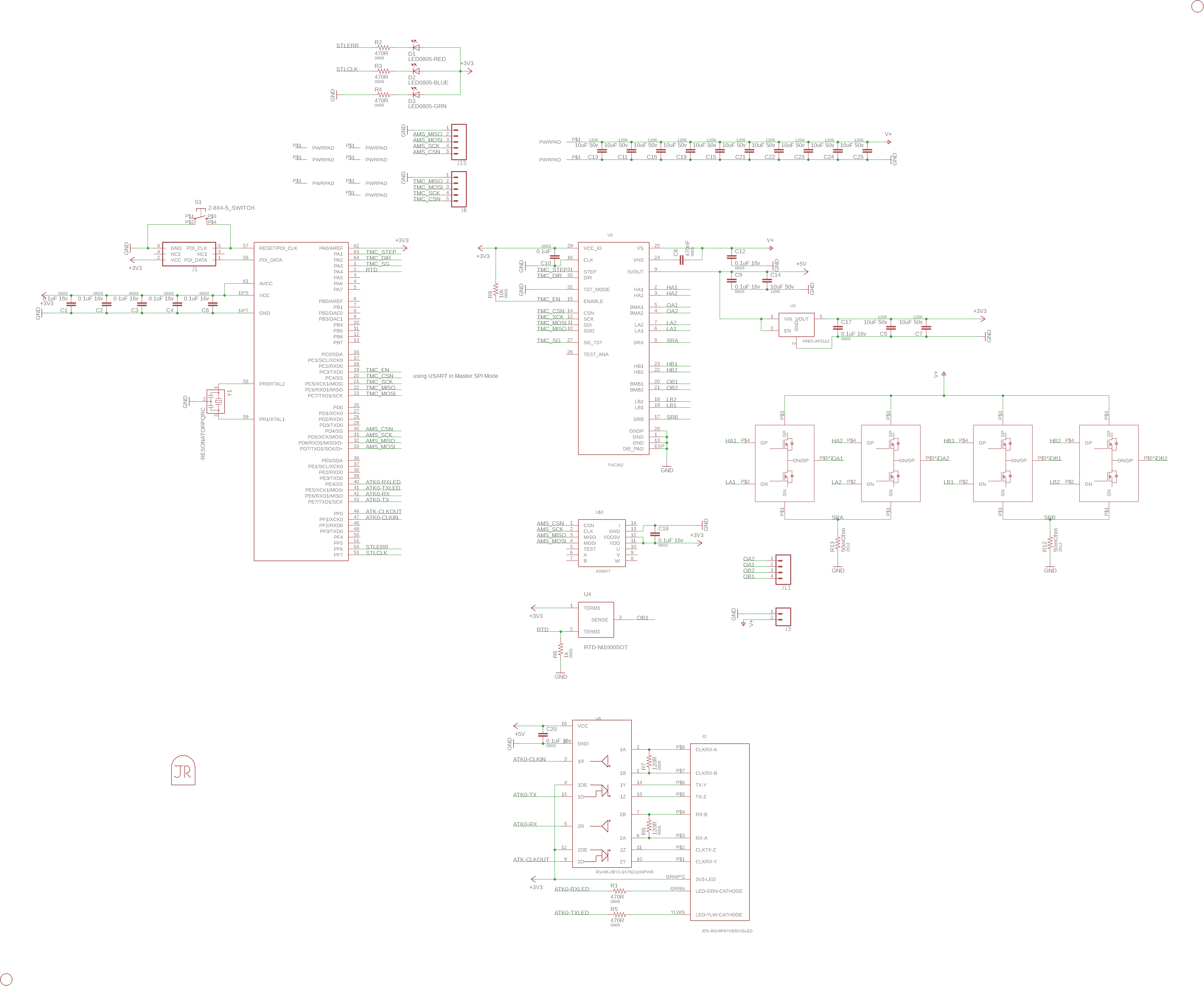
The circuit uses an ATXmega256A3U microcontroller and a TMC262 step gate-driver, with STI STL40C30H3ll P/N Pair Half Bridges to do the business. Between the driver and microcontroller are an SPI bus, to configure the driver, a diagnosis line, and step, direction, and enable lines.
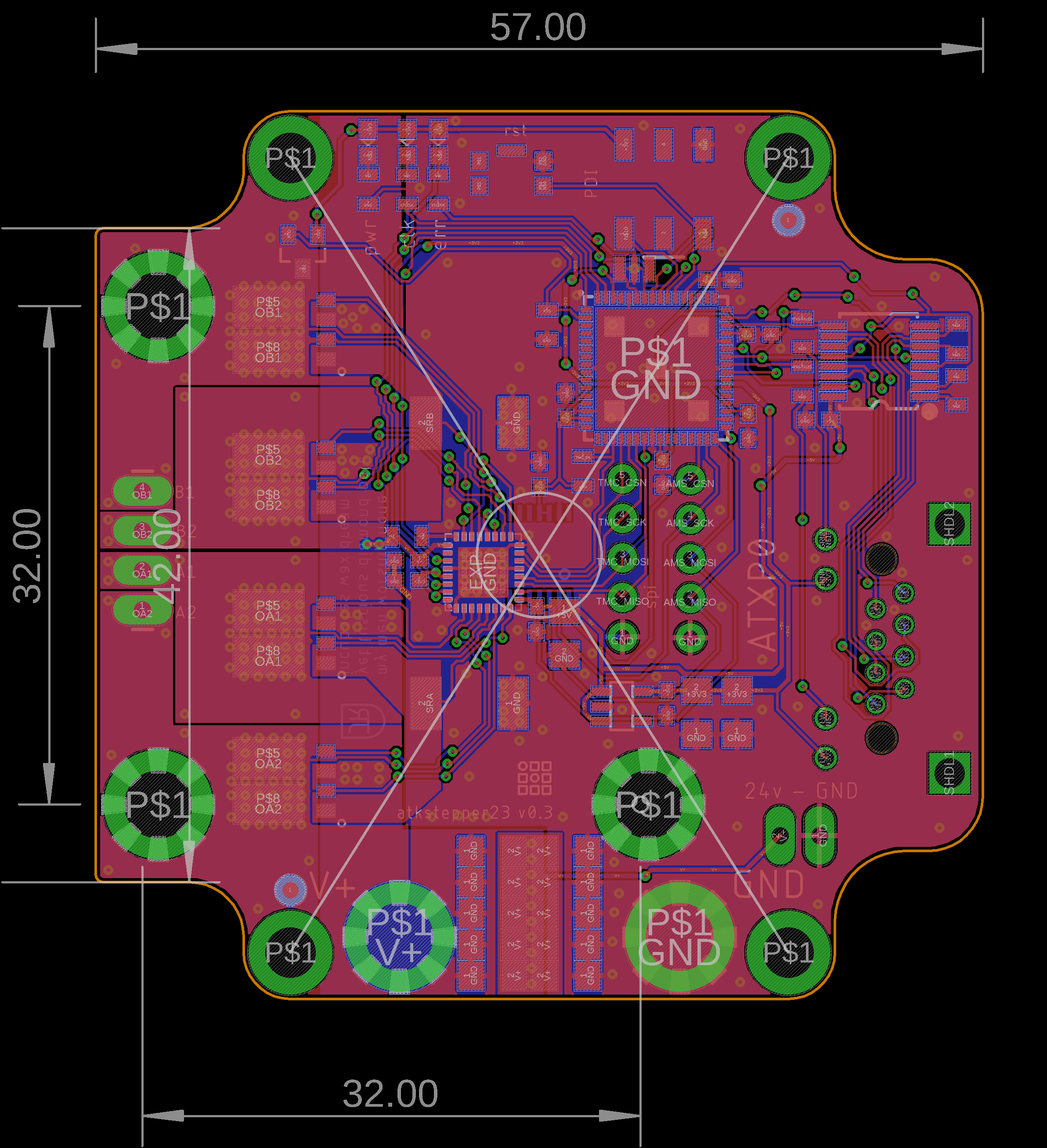
The Half-Bridges benefit from a heatsink mounted beneath them (heat is conducted through the IC's large bottom contacts, and through vias into the coppler plane below, and are rated to ~ 8A of current, but care needs to be taken to cool them down under these conditions. I have measured 110c board temperature at 1.5A without any heatsinking or airflow.
Power is bussed into the board with two M3 Screw Terminals. The board is not polarity protected. Data is delivered on two Automatakit Ports, which each include a data line (uart TX / RX) and clock lines (CLKIN and CLKOUT).
BOM
0.1uF 470nF 10uF
1k 470R 10k
Resonator LED Y,G,B RTD
SHNT 2520 PWRPAD 2x3 6PIN RJ45
RST BUTTON
XMEGA VREG-AP2112 RS-485-SN75C1168 TMC262 PNPAIR FDD8424 AS5047D